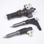
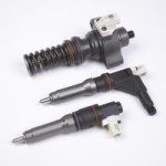
Delphi Launches Heavy-Duty Repair Program

Delphi Smart Injector and Electronic Unit Pump 300x200 Delphi Launches Heavy Duty Repair Program by Authcom, Nova Scotia\s Internet and Computing Solutions Provider in Kentville, Annapolis Valley

Delphi Product & Service Solutions (DPSS) announced the launch of its global Electronic Unit Pump (EUP) and Smart Injector repair program for high performance, heavy-duty (HD) applications. The product launch provides Delphi’s authorized repair network the potential service opportunity of almost two million EUP and Smart injector units.

Delphi’s EUP uses proven valve technology from Delphi’s EUI product Line. When used in conjunction with the high pressure electronically controlled Smart injector, the EUP provides a complete high pressure fuel delivery system for HD engines. The injectors nozzle control valve is electronically controlled, which helps to reduce fuel consumption and improve performance all while meeting the most stringent emissions regulations.

Delphi’s EUP and Smart Injector system is fitted to a wide range of DAF (MX and PR), Paccar and Yuchai applications for Euro 4, Euro 5 and US2010 emissions standards.

The repair solution will cover all EUP variants, and European specification Smart Injectors. This solution will be available as a test equipment upgrade package to current EUI E3 repair workshops. Repair for US2010 Smart Injectors will be available early 2015.

The launch also includes comprehensive support with new test equipment, updated IRIS software, dedicated repair tooling, training, and a rationalised repair parts program. Workshops who upgrade to EUP and Smart repair capability are required to attend the relevant training course held at one of Delphi’s global diesel training schools, before they are authorized to repair EUP and Smart Injectors.

The post Delphi Launches Heavy-Duty Repair Program appeared first on Engine Builder Magazine.

Read more here: Engine Builder Magazine

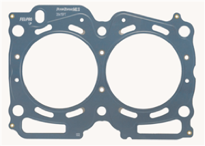
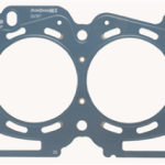
Fel-Pro PermaTorque Head Gasket

ca28d269 b313 4c78 88fd 1d940895ca09 thm.jpg Fel Pro PermaTorque Head Gasket by Authcom, Nova Scotia\s Internet and Computing Solutions Provider in Kentville, Annapolis Valley

Fel-Pro PermaTorque LaserWeld stopper layer design was first developed for Professional Stock Car racing engines, and is now available in Fel-Pro PermaTorque multi-layer-steel (MLS) head gaskets for a broad range of late-model automotive engines.

The new LaserWeld combustion seal ring provides a precisely determined and controlled limit to the compression of the multiple layers within the PermaTorque MLS head gasket, while ensuring proper sealing stress between the cylinder head and block. This helps reduce head lift commonly encountered in many late-model engines, prevents gasket damage and ensures a stronger, more superior combustion seal.

The post Fel-Pro PermaTorque Head Gasket appeared first on Engine Builder Magazine.

Read more here: Engine Builder Magazine

The Latest Improvements on Performance Cylinder Heads

head shot1170517 web 300x225 The Latest Improvements on Performance Cylinder Heads by Authcom, Nova Scotia\s Internet and Computing Solutions Provider in Kentville, Annapolis Valley

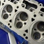
Heads are a product line that warrant almost constant research. Both the OEMs and aftermarket are creating new applications that solve problems, save time or money and just generally make life easier for engine builders. But, these improvements are only beneficial if those builders know what is out there waiting to help them.

So, we asked a number of cylinder head manufacturers about selection, technology, and even if the OEMs are doing it right. Some of their answers may amaze you, but they definitely will educate you on today’s heads.

We started with the ‘chicken or the egg’ of head questions – what are the best criteria for selecting a set of heads in a performance build. The basics are always best for this question, but, like knowing what is on the market, it’s always good to see what’s new.

For some high-end performance heads, a raw casting is CNC ­machined to specific dimensions for that application to deliver peak performance.

One Ohio-based manufacturer told us how he does it, “I have to know everything about the build and what it’s to be used for. Even about the driver and track size that it will be primarily used for and what the customer expects. And last but not least, how much money the customer has to spend. We find that a lot of potential customers can’t afford to do it the proper way. We ask that they do a little at a time so they aren’t spending their money twice or three times and getting discouraged and go and do some other form of entertainment.”

A California-located designer and manufacturer of cylinder heads provided his punch list, saying, “I would say the most import parameters to keep an eye on would be engine displacement, compression ratio, camshaft style, (and aggressiveness) RPM range, and application (street, drag, road race, marine, etc.) when selecting the ideal head for your project. Everything I just listed plays a large role in head selection with ‘compression ratio’ possibly playing the least importance, although an engine with high compression should automatically boost all the other parameters (more RPM, larger cam, etc.) helping by default to guide you into a larger, higher flowing head that would better fit that more aggressive application. The key is really looking at the intended application and building a motor purpose built to best optimize and compliment the type of power curve and engine manners that application dictates is best. A street car will always have compromises made in an effort to keep it friendly on the street so a smaller head than what you might consider in the same vehicle that only sees the strip is likely going to bring better overall results with the cam and other components also matched/selected to give it a more dual purpose personality. A high compression drag race engine is just the opposite. It lives from 5000 – 8000 RPM, hypothetically, and performance below 5K isn’t a consideration with larger, more aggressive cams, larger heads and manifold all make sense.

“The right combination of parts is paramount in extracting the most the heads have to offer in the particular environment you will be utilizing them – not only is selecting the right heads important, but the rest of the supporting bits and pieces as well,” he continued. “The hardest running engines are usually the most sorted out and perfectly optimized with all the components complimenting one another.”

An Alabama-based head manufacturer listed his top factors, “When a person is looking at a set of performance heads, there are several factors that figure into the equation. First off, is the size of the engine. I have customers all of the time that call and want to put a 225 runner cylinder head on a SBC 355. This is a deal where bigger is not better in most applications, which leads me to factor number two. Application; cruiser, street/strip or all-out race. This is a big factor because it determines the RPM range in which you want your engine to run its best. Another factor is the camshaft. This is what usually determines the spring package for each head. These are just a few of the factors we consider before we suggest a cylinder head for a customer. It’s been our experience to supply the proper size runner, combustion chamber, valve and springs for a total package that meets customer’s needs.”

The Tennessee racing head manufacturer agreed. “The basic criteria to begin with are the size of the engine, compression ratio, fuel type and application. Then, the engine builder needs to define their intended horsepower, torque and RPM band. This information will be used to identify the runner volume and combustion chamber size. The most common mistake we see is when individuals choose a larger runner volume head with impressive high-lift flow numbers. Unfortunately, these ‘big’ numbers do not necessarily translate into ‘big’ power for their application. Though the big flow numbers are impressive, they are not indicative of the performance of the engine. Quality of the airflow and the overall curve are much more important in achieving the desired outcome and making power and torque when and where needed.”

Another Ohio-based manufacturer added one more factor. “We feel the best criteria for selecting a set of cylinder heads is to know the cubic inches of the engine, the RPM you want to turn, the application and the weight of the car. From there, you can select the correct runner size and the amount of air flow required to support the engine.”

As head builders, our sources are even more tuned into the market than most folks. So we asked them for some of their intel on any new OEM technology on heads that may be a factor for engine builders now or in the future.

Head Games: Small block Chevy cylinder heads are installed during a COMP Cams Engine Builder Duel, as teams race against a clock in a performance engine building competition. Similar competitions are held at performance trade shows by seasoned engine builders, as well as youth, in competitions such as the Hot Rodders of Tomorrow.

The California manufacturer said, “Right now, the newest technology is DI (Direct Injection) where the fuel is sprayed under very high pressure ­directly into the combustion chamber instead of the manifold or intake port of the head. It’s much more ­precise and offers the end user more torque, more fuel economy, and more power. And my guess is most of the OEMs will be implementing this technology into their entire line up of cars in the next few years. Even the more sedate basic transportation models; in an effort to better meet the tightening CAFE standards ­without imparting power output in a negative fashion.”

While another head manufacturer echoed that with a simple, “direct injection issues” response, one of the spokespersons we interviewed sees a different issue. “The major thing that we see, which is not really new, is the overhead cam. It seems most engines on the OEM side are using this technology. I often wonder does this just complicate something that did not need complicating. We see cam journals damaged everyday on these heads. I can only speak of my personal experience, but I have had multiple Chevy trucks with 200,000 to 350,000 miles that I never had a moment’s trouble out of with the old push rod technology.”

Another aftermarket manufacturer addressed a different issue. “Today’s OEM heads are a big factor in the aftermarket. Gone are the days of ‘smog’ heads that choked down horsepower and limited the engine builder. Since the introduction of fuel injection and advancements in design software and computer aided modeling, the OEMs have had the ability to design fuel efficient, emission-friendly engines that still have the ability to make good horsepower.

“This has opened up the option for engine builders to use off-the-shelf parts that do not require a lot of modifications to achieve their performance goals. At the same time, it has educated the aftermarket and provided those folks with the ability to push the envelope a little further. In addition to improvements in the cylinder heads, the OEs have improved some of the valve train components that, with some inexpensive upgrades, can be used in performance applications.”

An Ohio manufacturer also addressed OEM technology. “As far as new technology from the OEMs, they are making progress, but you just can’t get the same performance from them that you can get from the aftermarket.”

With the proliferation of heads ­flying out of casting shops these days, we wondered what our sources have seen as far as any new technology in any OEM or ­aftermarket heads.

headscreated web 300x225 The Latest Improvements on Performance Cylinder Heads by Authcom, Nova Scotia\s Internet and Computing Solutions Provider in Kentville, Annapolis Valley

According to one cylinder head maker, the demand for larger, higher-flowing heads is just is one of the options engine builders are looking for when building today’s performance engines.

The Alabama supplier said he’s seen improvements, too.

“It seems to me that both the OEM and aftermarket head manufacturers are constantly raising the bar in performance. While this newest technology is usually expensive, it is amazing what is being done but right now. If I were putting together a performance application, give me an old school big block.”

The Tennessee supplier returned to the DI issue. “Direct injection is the latest technology that is being introduced at the OEM level. The placement of the injector into the combustion chamber allows the computer management system the ability to adjust the amount of fuel needed for the given condition, and lets it determine at what point of time during the combustion cycle fuel is needed.

“The result is more efficient combustion, which also results in more power with less waste. This is a big plus when the emissions in an OE application need to be limited. This technology is migrating into the aftermarket where we can utilize the OE architecture and adapt that technology to all-out performance applications without the limitations of fuel economy, emissions and manufacturing cost,” he said.”

The second Ohio manufacturer spoke on both the tech and production, “As far as new technology going into cylinder heads, we use a lot of wet flow development coupled with a CFD program when developing a new port or chamber design. Then, of course, we back that up with testing on the flow bench, dyno and race track.

“From a casting side, we are always looking into different alloys and processes that are being used in the Aerospace industry to see how they could benefit us in the aftermarket automotive performance business. And we are seeing some things there that look very promising,” he said.

The California supplier chimed in as well. “Variable valve timing comes to mind here as well. Some systems are more elaborate than others, but all of them are allowing the valve events to optimize the RPM range and load the driver commands with his right foot,” he said, adding, ”This allows an engine to act like it has a very small cam, down low, boosting MPG, low speed torque, and part throttle response. At the same time it’s able to hang on upstairs making big power at high RPM and not rolling over quickly past peak power (the camshaft events now optimized for that part of the RPM band).”

One of the Ohio head manufacturers said he hasn’t seen much in the way of new improved OE technology, yet opened up an area for a new product. “There’s nothing that I am impressed with. The new Vette LT motor is nice, but there is lots of improvements that could be made to the head layout.”

Lastly, we asked our sources what engine builders are asking for in new heads?

The West Coast manufacturer said they want products that they can build better with.

“Lighter components are popular and also the demand for larger, higher-flowing heads as the ability to build larger motors becomes more affordable (which then places a higher demand on the cylinder head to properly feed the larger “air pump” beneath them). This is truly the golden age of hot rodding with the largest difference being you can make big power now thanks to modern technology without paying the penalty of poor driving manners and poor fuel economy.”

Another supplier said the answer to what builders want is simple, “Engine builders want quality. And, they want to put their name on quality. We are constantly improving our products to offer the maximum quality and performance at a minimum price.”

One manufacturer responded that he sees more growth in engine sizes and performance.

head cart web 300x284 The Latest Improvements on Performance Cylinder Heads by Authcom, Nova Scotia\s Internet and Computing Solutions Provider in Kentville, Annapolis Valley“What we have been seeing engine builders ask for are cylinder heads to feed more cubic inches and turn more RPM. They want this and want to keep it user-friendly. This is what spurred the development of our new Sniper XL cylinder head. This is a 24 degree conventional BBC head that flows over 500 cfm. This cylinder head has been designed with all of the latest technology while working very closely with engine builders and other manufactures that will supply different parts for the head.”

Another manufacturer believes the LS market is really picking up steam. “We can offer builders the latest and greatest for all forms of racing. We also make heads that will stand 3500 HP of abuse.

The Midwest manufacturer also addressed tomorrow’s LS applications. “The cylinder head aftermarket is growing at a rapid rate. Larger cubic engines continue to push the airflow requirements from the cylinder heads. In addition, the trend towards late model engines continues to grow.

“We, too, place a lot of emphasis on our LS cylinder head line, where we offer a variety of runner, valve size and combustion chamber configurations to fit anything from a 3.900″ bore OE block all the way to heads to accommodate 500 CID with our LS block.

“The large cubic inch engines are not just limited to the race track, however, as they are becoming commonplace in the street market, too. Big cubic inch, high-horsepower pump gas engines are becoming the norm. We have also experienced a trend that our engine builders are looking to purchase heads that are ready to install right out of the box, from CNC-ported to fully assembled heads.

“In the past, most engine builders liked to put their finishing touches on the cylinder heads themselves, but with the variety of heads and options available today, and the quality components in our assembled heads, there is no need to invest additional labor hours.”

Heads have always been a quick fix for adding and even controlling how an engine runs. With today’s increasing selection of products and application, that quick fix can even receive a tune up.

The post The Latest Improvements on Performance Cylinder Heads appeared first on Engine Builder Magazine.

Read more here: Engine Builder Magazine

The Latest Improvements on Performance Cylinder Heads

head shot1170517 web 300x225 The Latest Improvements on Performance Cylinder Heads by Authcom, Nova Scotia\s Internet and Computing Solutions Provider in Kentville, Annapolis Valley

Heads are a product line that warrant almost constant research. Both the OEMs and aftermarket are creating new applications that solve problems, save time or money and just generally make life easier for engine builders. But, these improvements are only beneficial if those builders know what is out there waiting to help them.

So, we asked a number of cylinder head manufacturers about selection, technology, and even if the OEMs are doing it right. Some of their answers may amaze you, but they definitely will educate you on today’s heads.

We started with the ‘chicken or the egg’ of head questions – what are the best criteria for selecting a set of heads in a performance build. The basics are always best for this question, but, like knowing what is on the market, it’s always good to see what’s new.

For some high-end performance heads, a raw casting is CNC ­machined to specific dimensions for that application to deliver peak performance.

One Ohio-based manufacturer told us how he does it, “I have to know everything about the build and what it’s to be used for. Even about the driver and track size that it will be primarily used for and what the customer expects. And last but not least, how much money the customer has to spend. We find that a lot of potential customers can’t afford to do it the proper way. We ask that they do a little at a time so they aren’t spending their money twice or three times and getting discouraged and go and do some other form of entertainment.”

A California-located designer and manufacturer of cylinder heads provided his punch list, saying, “I would say the most import parameters to keep an eye on would be engine displacement, compression ratio, camshaft style, (and aggressiveness) RPM range, and application (street, drag, road race, marine, etc.) when selecting the ideal head for your project. Everything I just listed plays a large role in head selection with ‘compression ratio’ possibly playing the least importance, although an engine with high compression should automatically boost all the other parameters (more RPM, larger cam, etc.) helping by default to guide you into a larger, higher flowing head that would better fit that more aggressive application. The key is really looking at the intended application and building a motor purpose built to best optimize and compliment the type of power curve and engine manners that application dictates is best. A street car will always have compromises made in an effort to keep it friendly on the street so a smaller head than what you might consider in the same vehicle that only sees the strip is likely going to bring better overall results with the cam and other components also matched/selected to give it a more dual purpose personality. A high compression drag race engine is just the opposite. It lives from 5000 – 8000 RPM, hypothetically, and performance below 5K isn’t a consideration with larger, more aggressive cams, larger heads and manifold all make sense.

“The right combination of parts is paramount in extracting the most the heads have to offer in the particular environment you will be utilizing them – not only is selecting the right heads important, but the rest of the supporting bits and pieces as well,” he continued. “The hardest running engines are usually the most sorted out and perfectly optimized with all the components complimenting one another.”

An Alabama-based head manufacturer listed his top factors, “When a person is looking at a set of performance heads, there are several factors that figure into the equation. First off, is the size of the engine. I have customers all of the time that call and want to put a 225 runner cylinder head on a SBC 355. This is a deal where bigger is not better in most applications, which leads me to factor number two. Application; cruiser, street/strip or all-out race. This is a big factor because it determines the RPM range in which you want your engine to run its best. Another factor is the camshaft. This is what usually determines the spring package for each head. These are just a few of the factors we consider before we suggest a cylinder head for a customer. It’s been our experience to supply the proper size runner, combustion chamber, valve and springs for a total package that meets customer’s needs.”

The Tennessee racing head manufacturer agreed. “The basic criteria to begin with are the size of the engine, compression ratio, fuel type and application. Then, the engine builder needs to define their intended horsepower, torque and RPM band. This information will be used to identify the runner volume and combustion chamber size. The most common mistake we see is when individuals choose a larger runner volume head with impressive high-lift flow numbers. Unfortunately, these ‘big’ numbers do not necessarily translate into ‘big’ power for their application. Though the big flow numbers are impressive, they are not indicative of the performance of the engine. Quality of the airflow and the overall curve are much more important in achieving the desired outcome and making power and torque when and where needed.”

Another Ohio-based manufacturer added one more factor. “We feel the best criteria for selecting a set of cylinder heads is to know the cubic inches of the engine, the RPM you want to turn, the application and the weight of the car. From there, you can select the correct runner size and the amount of air flow required to support the engine.”

As head builders, our sources are even more tuned into the market than most folks. So we asked them for some of their intel on any new OEM technology on heads that may be a factor for engine builders now or in the future.

Head Games: Small block Chevy cylinder heads are installed during a COMP Cams Engine Builder Duel, as teams race against a clock in a performance engine building competition. Similar competitions are held at performance trade shows by seasoned engine builders, as well as youth, in competitions such as the Hot Rodders of Tomorrow.

The California manufacturer said, “Right now, the newest technology is DI (Direct Injection) where the fuel is sprayed under very high pressure ­directly into the combustion chamber instead of the manifold or intake port of the head. It’s much more ­precise and offers the end user more torque, more fuel economy, and more power. And my guess is most of the OEMs will be implementing this technology into their entire line up of cars in the next few years. Even the more sedate basic transportation models; in an effort to better meet the tightening CAFE standards ­without imparting power output in a negative fashion.”

While another head manufacturer echoed that with a simple, “direct injection issues” response, one of the spokespersons we interviewed sees a different issue. “The major thing that we see, which is not really new, is the overhead cam. It seems most engines on the OEM side are using this technology. I often wonder does this just complicate something that did not need complicating. We see cam journals damaged everyday on these heads. I can only speak of my personal experience, but I have had multiple Chevy trucks with 200,000 to 350,000 miles that I never had a moment’s trouble out of with the old push rod technology.”

Another aftermarket manufacturer addressed a different issue. “Today’s OEM heads are a big factor in the aftermarket. Gone are the days of ‘smog’ heads that choked down horsepower and limited the engine builder. Since the introduction of fuel injection and advancements in design software and computer aided modeling, the OEMs have had the ability to design fuel efficient, emission-friendly engines that still have the ability to make good horsepower.

“This has opened up the option for engine builders to use off-the-shelf parts that do not require a lot of modifications to achieve their performance goals. At the same time, it has educated the aftermarket and provided those folks with the ability to push the envelope a little further. In addition to improvements in the cylinder heads, the OEs have improved some of the valve train components that, with some inexpensive upgrades, can be used in performance applications.”

An Ohio manufacturer also addressed OEM technology. “As far as new technology from the OEMs, they are making progress, but you just can’t get the same performance from them that you can get from the aftermarket.”

With the proliferation of heads ­flying out of casting shops these days, we wondered what our sources have seen as far as any new technology in any OEM or ­aftermarket heads.

headscreated web 300x225 The Latest Improvements on Performance Cylinder Heads by Authcom, Nova Scotia\s Internet and Computing Solutions Provider in Kentville, Annapolis Valley

According to one cylinder head maker, the demand for larger, higher-flowing heads is just is one of the options engine builders are looking for when building today’s performance engines.

The Alabama supplier said he’s seen improvements, too.

“It seems to me that both the OEM and aftermarket head manufacturers are constantly raising the bar in performance. While this newest technology is usually expensive, it is amazing what is being done but right now. If I were putting together a performance application, give me an old school big block.”

The Tennessee supplier returned to the DI issue. “Direct injection is the latest technology that is being introduced at the OEM level. The placement of the injector into the combustion chamber allows the computer management system the ability to adjust the amount of fuel needed for the given condition, and lets it determine at what point of time during the combustion cycle fuel is needed.

“The result is more efficient combustion, which also results in more power with less waste. This is a big plus when the emissions in an OE application need to be limited. This technology is migrating into the aftermarket where we can utilize the OE architecture and adapt that technology to all-out performance applications without the limitations of fuel economy, emissions and manufacturing cost,” he said.”

The second Ohio manufacturer spoke on both the tech and production, “As far as new technology going into cylinder heads, we use a lot of wet flow development coupled with a CFD program when developing a new port or chamber design. Then, of course, we back that up with testing on the flow bench, dyno and race track.

“From a casting side, we are always looking into different alloys and processes that are being used in the Aerospace industry to see how they could benefit us in the aftermarket automotive performance business. And we are seeing some things there that look very promising,” he said.

The California supplier chimed in as well. “Variable valve timing comes to mind here as well. Some systems are more elaborate than others, but all of them are allowing the valve events to optimize the RPM range and load the driver commands with his right foot,” he said, adding, ”This allows an engine to act like it has a very small cam, down low, boosting MPG, low speed torque, and part throttle response. At the same time it’s able to hang on upstairs making big power at high RPM and not rolling over quickly past peak power (the camshaft events now optimized for that part of the RPM band).”

One of the Ohio head manufacturers said he hasn’t seen much in the way of new improved OE technology, yet opened up an area for a new product. “There’s nothing that I am impressed with. The new Vette LT motor is nice, but there is lots of improvements that could be made to the head layout.”

Lastly, we asked our sources what engine builders are asking for in new heads?

The West Coast manufacturer said they want products that they can build better with.

“Lighter components are popular and also the demand for larger, higher-flowing heads as the ability to build larger motors becomes more affordable (which then places a higher demand on the cylinder head to properly feed the larger “air pump” beneath them). This is truly the golden age of hot rodding with the largest difference being you can make big power now thanks to modern technology without paying the penalty of poor driving manners and poor fuel economy.”

Another supplier said the answer to what builders want is simple, “Engine builders want quality. And, they want to put their name on quality. We are constantly improving our products to offer the maximum quality and performance at a minimum price.”

One manufacturer responded that he sees more growth in engine sizes and performance.

head cart web 300x284 The Latest Improvements on Performance Cylinder Heads by Authcom, Nova Scotia\s Internet and Computing Solutions Provider in Kentville, Annapolis Valley“What we have been seeing engine builders ask for are cylinder heads to feed more cubic inches and turn more RPM. They want this and want to keep it user-friendly. This is what spurred the development of our new Sniper XL cylinder head. This is a 24 degree conventional BBC head that flows over 500 cfm. This cylinder head has been designed with all of the latest technology while working very closely with engine builders and other manufactures that will supply different parts for the head.”

Another manufacturer believes the LS market is really picking up steam. “We can offer builders the latest and greatest for all forms of racing. We also make heads that will stand 3500 HP of abuse.

The Midwest manufacturer also addressed tomorrow’s LS applications. “The cylinder head aftermarket is growing at a rapid rate. Larger cubic engines continue to push the airflow requirements from the cylinder heads. In addition, the trend towards late model engines continues to grow.

“We, too, place a lot of emphasis on our LS cylinder head line, where we offer a variety of runner, valve size and combustion chamber configurations to fit anything from a 3.900″ bore OE block all the way to heads to accommodate 500 CID with our LS block.

“The large cubic inch engines are not just limited to the race track, however, as they are becoming commonplace in the street market, too. Big cubic inch, high-horsepower pump gas engines are becoming the norm. We have also experienced a trend that our engine builders are looking to purchase heads that are ready to install right out of the box, from CNC-ported to fully assembled heads.

“In the past, most engine builders liked to put their finishing touches on the cylinder heads themselves, but with the variety of heads and options available today, and the quality components in our assembled heads, there is no need to invest additional labor hours.”

Heads have always been a quick fix for adding and even controlling how an engine runs. With today’s increasing selection of products and application, that quick fix can even receive a tune up.

The post The Latest Improvements on Performance Cylinder Heads appeared first on Engine Builder Magazine.

Read more here: Engine Builder Magazine
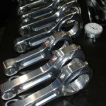
Replacing Crankshafts, Connecting Rods and Bearings

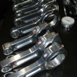
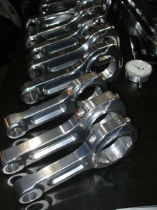
connecting rods unknown brand web 225x300 Replacing Crankshafts, Connecting Rods and Bearings by Authcom, Nova Scotia\s Internet and Computing Solutions Provider in Kentville, Annapolis Valley

The crankshaft, connecting rods and bearings are extremely important in every engine build, whether mild or wild, because they convert the reciprocating motion of the pistons into rotational torque. The longer the stroke, the greater the leverage effect and the greater the torque output of the engine. There are three things that need to be considered when replacing a crank, rods and bearings:

1. Strength — Are the parts going to be strong enough for their intended use? A circle track car, drag car or marine application will put far more strain on the crank and rods than a stock or street performance daily driver.

2. Bearing clearances — Are you going to build it loose or tight? Will the oil viscosity and pressure match the bearing clearances?

3. Balance — Absolutely critical for engine longevity regardless of the application or RPM potential of the engine. Even a small imbalance at low RPM over a long period of time can fatigue metal.

The correct length is vital when selecting connecting rods. Rod ratio is the length of a connecting rod (center to center) divided by the stroke of the crankshaft.

Durability

Stock engines and street performance engines are expected to last a long time: tens of thousands of miles if not a 100,000 miles or more. Combustion temperatures and pressures are lower in a stock engine than a performance engine, and RPM is usually limited to about 6,500 RPM or less. Consequently, a cast iron crankshaft, original equipment powder metal rods and standard bearings are usually adequate for their intended use.

Original equipment cast iron cranks are usually made of 1053 high-carbon alloy steel. This material has a tensile strength of around 100,000 to 110,000 psi, which can usually handle as much as 400 to 450 horsepower (depending on the engine and size of the journals). Forged cranks, by comparison, may be made from 5140, 4130, 4340 or other high grade alloy steels with tensile strength ratings from 115,000 psi up to 165,000 psi or higher (depending on the alloy and heat treatment). Essentially, you get what you pay for when you buy a high performance crank made of a high quality alloy.

Most of the forgings that are used in aftermarket performance cranks today come from China. The quality of the metal depends on the supplier and how the crank is heat treated. Some U.S. crank suppliers do their own finishing work and heat treatment on the Chinese-forgings they buy while others go with prefinished cranks. What’s really important here is not the source of the crank or the brand on the box but the quality that has gone into manufacturing and finishing the product. The journals on a high performance crank should be perfectly round and polished to specifications, and level side to side with no taper or convex or concave curvature. The location of the journals must also be accurately indexed for proper valve timing and ignition. The counterweights must also be in the right locations and have the proper mass to offset the reciprocating mass of the pistons and rods. As long as a crank meets all of these criteria, it should be a good, dependable crank.

Crankshafts can fail if they are subjected to more power than they can handle, and from metal fatigue. Asking a stock cast iron crank to handle more than 400 to 450 horsepower in a small block V8, or over 550 horsepower in many big blocks is asking for trouble. If the engine will be equipped with some type of power added (nitrous oxide, a turbocharger or supercharger), the demands on the crank will go up even more and likely require an upgrade to a forged or billet steel performance crank.

Do you want a light crank or a heavy crank? It depends on the application for which you are building the engine. Circle track cars are probably the most demanding on both the crank and rods because the engine is constantly on and off the throttle. If the rules allow it, a lightweight crank will provide better throttle response and allow the engine to rev and decel more quickly than a stock weight crank. On the other hand, if you are building an engine for a drag car, weight doesn’t matter because the engine will be running at full throttle for a quarter of a mile. The extra rotating weight will also add momentum that can help a car launch off the line without bogging.

Another point to keep in mind if you are building a blown engine is the extra stress the blower drive puts on the end of the crank. The added stress and flexing over time can lead to fatigue cracks and crank breakage, so look for a crank that is available with a larger diameter nose.

Choosing a rod depends on the ­application – you want a rod that’s strong enough to handle the power and RPMs the engine is capable of producing.

Upgrading Rods

Many late model engines are factory equipped with powder metal rods. The vehicle manufacturers like powder metal rods because they are much less expensive to manufacture. The rods can be cast to very close final tolerances and require less machining than a cast iron or forged steel connecting rod. There is no grain structure in a powder metal rod so the rods can be cracked to separate the cap from the rod. This is faster, easier and some say better than cutting and machining rod caps because cracking leaves a slightly jagged surface on the cap and rod which will only mate together one way. The advantage is that it provides perfect alignment between the cap and rod but the trade-off is that the cap and rod cannot be machined to correct for any bore distortion or wear that has occurred over time. Because of this, powder metal rods are essentially throwaways if the big end is worn or the cap has loosened up over time (which they do).

If you’re doing a performance build, therefore, one of the first parts that will have to be upgraded is the rods. Replace the original equipment powder metal rods with some type of aftermarket performance rod (I-beam or H-beam).

There are a lot of choices when it comes to aftermarket rods. Choosing a rod depends again on the application. You want a rod that’s strong enough to handle the power and RPMs the engine is capable of producing. You also have to match the rod length with the stroke of the crank, the pistons and pin location, and the engine’s deck height.

Strength is critical in a connecting rod. The forces that stretch and compress the rods exert tremendous stress on the beam section of the rod. If a rod is going to fail, it will most often pull apart on a piston upstroke rather than bend during a piston downstroke. A rod can also fail if the bearing starves for oil, seizes and rips the rod apart.

The stock rods in most V8s are stout enough to handle upwards of 400 to 450 horsepower, and 5,500 to 6,500 RPM. Exceed these limits and you’ll need stronger rods for reliability. One aftermarket rod supplier we interviewed for this article said his entry level rods can handle 800 to 990 horsepower, and his top end rods are running in engines producing upwards of 2000 horsepower. H-beam rods made of 4340 or 300M steel are commonly used in many circle track engines, while I-beam rods are popular with drag racers and marine engine builders. The debate of I-Beam versus H-Beam often boils down to a matter of personal preference.

Most Top Fuel dragsters and funny cars use aluminum rods in their motors. So do many ProStock racers. Aluminum rods have a limited service life because they can stretch and fatigue in high stress engines like these. Even so, they work well enough because the typical Top Fuel racer replaces the rods after 8 to 10 runs. ProStock racers may replace the rods after 20 or 30 runs. In the lower drag racing classes, a set of aluminum rods may last 100 to 200 runs or longer.

Aluminum rods can work on the street, but it requires a high quality alloy. For this reason, many engine builders prefer to stick with steel rods for their proven longevity.

Titanium rods are another option for those with deep pockets. Titanium is light weight (about 24% lighter than a comparable steel rod) and has about the same durability as a steel rod, but titanium is expensive and tricky to manufacture. If you can afford them, great! Otherwise, they are probably too expensive for the average street performance customer or weekend racer.

Rod length is another choice you will have to make when selecting a set of rods. Rod ratio is the length of a connecting rod (center to center) divided by the stroke of the crankshaft. Many performance engine builders say a rod ratio of 1.57 to 1.67 works best. A longer rod ratio can make an engine’s torque output peak more sharply. Lower rod ratios work well with lower RPM stroker motors while higher rod ratios are better suited for high revving engines.

Another option is to use rods that do not have wrist pin bushings. This leaves more metal around the wrist pin for added strength at high RPM. But it requires a highly polished pin hole and a low friction coating on the wrist pin to prevent the pin from galling.

The type of bolts used to attach the rod cap to the rod is also important. The stronger the bolts, the better. Poor quality bolts can stretch and allow the cap to wander, leading to rod and bearing failure.

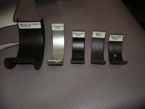
bearing coatings web 300x225 Replacing Crankshafts, Connecting Rods and Bearings by Authcom, Nova Scotia\s Internet and Computing Solutions Provider in Kentville, Annapolis Valley

Reducing the oil clearance between the rod and main bearings and the crankshaft has a number of advantages. A smaller gap spreads the load over a wider area of the bearing surface and distributes pressure more uniformly across the bearing.

Bearings

The bearings support the crank and bear the forces that are exerted by the rods as they reciprocate up and down. A thin film of oil is all that separates the bearing from the crank journals, so bearing clearances as well as oil viscosity and oil pressure must all be considered when building an engine for a particular application.

Traditionally, most performance engine builders have gone with “looser” bearing clearances (.0025 to .003 inches) for the rod and main bearings because it works well with 15W-40 racing oil and high pressure oil pumps. One crankshaft manufacturer said the larger the journals on the crank, the more bearing clearance you should allow so the oil can get all the way around the bearing. If you set the bearings too close, you run the risk of spinning a bearing.

On some applications, tight clearances work provided the right combination of shaft diameter, bearing clearance, oil viscosity and oil pressure is used. A tighter bearing clearance spreads the load over a slightly broader arc on the bearing whereas a larger bearing clearance will concentrate the load on a narrower strip of the bearing surface. Spreading the load across a larger area of the bearing is good in an endurance engine and street engine because it reduces metal fatigue and extends the life of the bearing.

Indy cars and NASCAR can get away with tight bearing clearances (.0015 or less) because many of these engines have smaller diameter cranks and they are using low viscosity 0W-40 or 5W-20 synthetic racing oils.

The crank journals also have excellent geometry and are finished to precise tolerances (which may not always be the case with a budget motor or a reground crank). The tighter clearances and thinner oil means less oil pressure is needed to keep the bearings lubed, so oil pressure can be reduced to cut the amount of power needed to drive a wet dump oil pump. Thinner oils also reduce friction which saves horsepower.

The disadvantage of thinner viscosity oils is that the oil can drain off the bearings more quickly. When a race car sits all week without running, the bearings may be dry when the engine is fired up. A heavier oil will cling to the bearings better, but will require more bearing clearance so it will flow around the bearings more easily.

It goes without saying that journal diameters and well as bearing fit should always be measured when assembling an engine. Never assume everything has been manufactured to specifications or has been boxed accurately. Mistakes happen!

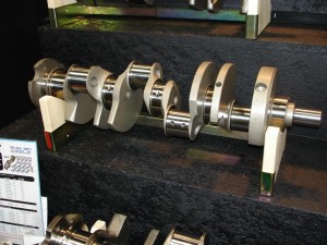
crank scat 1 web 300x225 Replacing Crankshafts, Connecting Rods and Bearings by Authcom, Nova Scotia\s Internet and Computing Solutions Provider in Kentville, Annapolis Valley

The journals on a high performance crank should be perfectly round and polished to specifications.
Photo courtesy of Scat Enterprises Inc.

Balance Considerations

Whether an engine is internally balanced (usually preferred) or externally balanced, a good balance is essential for crank and bearing longevity. Imbalance in the rotating assembly creates shaking forces that can fatigue metal over time. The closer the balance, the better — even in engines that seldom if ever see the high side of 5500 RPM. Imbalance grows exponentially with engine speed, so the higher the engine revs the greater the force generated by even a small imbalance.

When choosing a replacement crank, you want to match the weight of the rods, wrist pins, pistons and rings to the counterweights on the crank.

All crankshafts have a target bobweight (plus or minus 2 percent typically) that approximates the weights of the pistons and rods that you plan to use. The closer the target bobweight of the crank is to the actual parts, the less time and drilling it will take to balance the crank.

Determining the bobweight requires weighing all of the parts. Rod weights tend to vary more than piston weights due to heavier mass.

With lightweight cranks or those where the outside diameter of the counterweights have been turned down to reduce weight, there may not be enough metal in the counterweights to completely offset the pistons and rods. This will require heavy metal tungsten (Mallory) plugs in the counterweights to balance the crank and possibly externally balance the engine with additional weight on the flywheel and harmonic balancer. Heavy metal adds cost as well as extra time and labor to balance the crank.

Most production V8 crankshafts have six counterweights to reduce weight and cost. This works well enough for most applications, including racing. But for high revving endurance engines and longer stroke engines, adding two additional counterweights for the center pistons allows better balance and reduces crank flexing that can lead to fatigue and crank failure.

Some cranks have holes drilled lengthwise through the main journals. This has no effect on balance and only reduces the overall weight of the crank maybe 2 or 3 lbs. The main purpose of these holes is to allow air to move back and forth in the crankcase as the pistons move up and down. On Chevy LS engines, this type of breathing is essential because the crankcase is very tight and restricts airflow between cylinders.

If you are installing a windage tray on a Chevy LS, the tray needs to be positioned far enough away from the crank so that it doesn’t inhibit this back and forth airflow within the crankcase.

The tray needs to be above the oil level in the pan so oil is whipped up by the spinning crank, but at least an inch or more away from the crank to allow good airflow.

A dry sump oil system that has enough suction to pull vacuum in the crankcase will solve such breathing problems by pulling out most of the air along with the oil.

The post Replacing Crankshafts, Connecting Rods and Bearings appeared first on Engine Builder Magazine.

Read more here: Engine Builder Magazine

Replacing Crankshafts, Connecting Rods and Bearings

connecting rods unknown brand web 225x300 Replacing Crankshafts, Connecting Rods and Bearings by Authcom, Nova Scotia\s Internet and Computing Solutions Provider in Kentville, Annapolis Valley

The crankshaft, connecting rods and bearings are extremely important in every engine build, whether mild or wild, because they convert the reciprocating motion of the pistons into rotational torque. The longer the stroke, the greater the leverage effect and the greater the torque output of the engine. There are three things that need to be considered when replacing a crank, rods and bearings:

1. Strength — Are the parts going to be strong enough for their intended use? A circle track car, drag car or marine application will put far more strain on the crank and rods than a stock or street performance daily driver.

2. Bearing clearances — Are you going to build it loose or tight? Will the oil viscosity and pressure match the bearing clearances?

3. Balance — Absolutely critical for engine longevity regardless of the application or RPM potential of the engine. Even a small imbalance at low RPM over a long period of time can fatigue metal.

The correct length is vital when selecting connecting rods. Rod ratio is the length of a connecting rod (center to center) divided by the stroke of the crankshaft.

Durability

Stock engines and street performance engines are expected to last a long time: tens of thousands of miles if not a 100,000 miles or more. Combustion temperatures and pressures are lower in a stock engine than a performance engine, and RPM is usually limited to about 6,500 RPM or less. Consequently, a cast iron crankshaft, original equipment powder metal rods and standard bearings are usually adequate for their intended use.

Original equipment cast iron cranks are usually made of 1053 high-carbon alloy steel. This material has a tensile strength of around 100,000 to 110,000 psi, which can usually handle as much as 400 to 450 horsepower (depending on the engine and size of the journals). Forged cranks, by comparison, may be made from 5140, 4130, 4340 or other high grade alloy steels with tensile strength ratings from 115,000 psi up to 165,000 psi or higher (depending on the alloy and heat treatment). Essentially, you get what you pay for when you buy a high performance crank made of a high quality alloy.

Most of the forgings that are used in aftermarket performance cranks today come from China. The quality of the metal depends on the supplier and how the crank is heat treated. Some U.S. crank suppliers do their own finishing work and heat treatment on the Chinese-forgings they buy while others go with prefinished cranks. What’s really important here is not the source of the crank or the brand on the box but the quality that has gone into manufacturing and finishing the product. The journals on a high performance crank should be perfectly round and polished to specifications, and level side to side with no taper or convex or concave curvature. The location of the journals must also be accurately indexed for proper valve timing and ignition. The counterweights must also be in the right locations and have the proper mass to offset the reciprocating mass of the pistons and rods. As long as a crank meets all of these criteria, it should be a good, dependable crank.

Crankshafts can fail if they are subjected to more power than they can handle, and from metal fatigue. Asking a stock cast iron crank to handle more than 400 to 450 horsepower in a small block V8, or over 550 horsepower in many big blocks is asking for trouble. If the engine will be equipped with some type of power added (nitrous oxide, a turbocharger or supercharger), the demands on the crank will go up even more and likely require an upgrade to a forged or billet steel performance crank.

Do you want a light crank or a heavy crank? It depends on the application for which you are building the engine. Circle track cars are probably the most demanding on both the crank and rods because the engine is constantly on and off the throttle. If the rules allow it, a lightweight crank will provide better throttle response and allow the engine to rev and decel more quickly than a stock weight crank. On the other hand, if you are building an engine for a drag car, weight doesn’t matter because the engine will be running at full throttle for a quarter of a mile. The extra rotating weight will also add momentum that can help a car launch off the line without bogging.

Another point to keep in mind if you are building a blown engine is the extra stress the blower drive puts on the end of the crank. The added stress and flexing over time can lead to fatigue cracks and crank breakage, so look for a crank that is available with a larger diameter nose.

Choosing a rod depends on the ­application – you want a rod that’s strong enough to handle the power and RPMs the engine is capable of producing.

Upgrading Rods

Many late model engines are factory equipped with powder metal rods. The vehicle manufacturers like powder metal rods because they are much less expensive to manufacture. The rods can be cast to very close final tolerances and require less machining than a cast iron or forged steel connecting rod. There is no grain structure in a powder metal rod so the rods can be cracked to separate the cap from the rod. This is faster, easier and some say better than cutting and machining rod caps because cracking leaves a slightly jagged surface on the cap and rod which will only mate together one way. The advantage is that it provides perfect alignment between the cap and rod but the trade-off is that the cap and rod cannot be machined to correct for any bore distortion or wear that has occurred over time. Because of this, powder metal rods are essentially throwaways if the big end is worn or the cap has loosened up over time (which they do).

If you’re doing a performance build, therefore, one of the first parts that will have to be upgraded is the rods. Replace the original equipment powder metal rods with some type of aftermarket performance rod (I-beam or H-beam).

There are a lot of choices when it comes to aftermarket rods. Choosing a rod depends again on the application. You want a rod that’s strong enough to handle the power and RPMs the engine is capable of producing. You also have to match the rod length with the stroke of the crank, the pistons and pin location, and the engine’s deck height.

Strength is critical in a connecting rod. The forces that stretch and compress the rods exert tremendous stress on the beam section of the rod. If a rod is going to fail, it will most often pull apart on a piston upstroke rather than bend during a piston downstroke. A rod can also fail if the bearing starves for oil, seizes and rips the rod apart.

The stock rods in most V8s are stout enough to handle upwards of 400 to 450 horsepower, and 5,500 to 6,500 RPM. Exceed these limits and you’ll need stronger rods for reliability. One aftermarket rod supplier we interviewed for this article said his entry level rods can handle 800 to 990 horsepower, and his top end rods are running in engines producing upwards of 2000 horsepower. H-beam rods made of 4340 or 300M steel are commonly used in many circle track engines, while I-beam rods are popular with drag racers and marine engine builders. The debate of I-Beam versus H-Beam often boils down to a matter of personal preference.

Most Top Fuel dragsters and funny cars use aluminum rods in their motors. So do many ProStock racers. Aluminum rods have a limited service life because they can stretch and fatigue in high stress engines like these. Even so, they work well enough because the typical Top Fuel racer replaces the rods after 8 to 10 runs. ProStock racers may replace the rods after 20 or 30 runs. In the lower drag racing classes, a set of aluminum rods may last 100 to 200 runs or longer.

Aluminum rods can work on the street, but it requires a high quality alloy. For this reason, many engine builders prefer to stick with steel rods for their proven longevity.

Titanium rods are another option for those with deep pockets. Titanium is light weight (about 24% lighter than a comparable steel rod) and has about the same durability as a steel rod, but titanium is expensive and tricky to manufacture. If you can afford them, great! Otherwise, they are probably too expensive for the average street performance customer or weekend racer.

Rod length is another choice you will have to make when selecting a set of rods. Rod ratio is the length of a connecting rod (center to center) divided by the stroke of the crankshaft. Many performance engine builders say a rod ratio of 1.57 to 1.67 works best. A longer rod ratio can make an engine’s torque output peak more sharply. Lower rod ratios work well with lower RPM stroker motors while higher rod ratios are better suited for high revving engines.

Another option is to use rods that do not have wrist pin bushings. This leaves more metal around the wrist pin for added strength at high RPM. But it requires a highly polished pin hole and a low friction coating on the wrist pin to prevent the pin from galling.

The type of bolts used to attach the rod cap to the rod is also important. The stronger the bolts, the better. Poor quality bolts can stretch and allow the cap to wander, leading to rod and bearing failure.

bearing coatings web 300x225 Replacing Crankshafts, Connecting Rods and Bearings by Authcom, Nova Scotia\s Internet and Computing Solutions Provider in Kentville, Annapolis Valley

Reducing the oil clearance between the rod and main bearings and the crankshaft has a number of advantages. A smaller gap spreads the load over a wider area of the bearing surface and distributes pressure more uniformly across the bearing.

Bearings

The bearings support the crank and bear the forces that are exerted by the rods as they reciprocate up and down. A thin film of oil is all that separates the bearing from the crank journals, so bearing clearances as well as oil viscosity and oil pressure must all be considered when building an engine for a particular application.

Traditionally, most performance engine builders have gone with “looser” bearing clearances (.0025 to .003 inches) for the rod and main bearings because it works well with 15W-40 racing oil and high pressure oil pumps. One crankshaft manufacturer said the larger the journals on the crank, the more bearing clearance you should allow so the oil can get all the way around the bearing. If you set the bearings too close, you run the risk of spinning a bearing.

On some applications, tight clearances work provided the right combination of shaft diameter, bearing clearance, oil viscosity and oil pressure is used. A tighter bearing clearance spreads the load over a slightly broader arc on the bearing whereas a larger bearing clearance will concentrate the load on a narrower strip of the bearing surface. Spreading the load across a larger area of the bearing is good in an endurance engine and street engine because it reduces metal fatigue and extends the life of the bearing.

Indy cars and NASCAR can get away with tight bearing clearances (.0015 or less) because many of these engines have smaller diameter cranks and they are using low viscosity 0W-40 or 5W-20 synthetic racing oils.

The crank journals also have excellent geometry and are finished to precise tolerances (which may not always be the case with a budget motor or a reground crank). The tighter clearances and thinner oil means less oil pressure is needed to keep the bearings lubed, so oil pressure can be reduced to cut the amount of power needed to drive a wet dump oil pump. Thinner oils also reduce friction which saves horsepower.

The disadvantage of thinner viscosity oils is that the oil can drain off the bearings more quickly. When a race car sits all week without running, the bearings may be dry when the engine is fired up. A heavier oil will cling to the bearings better, but will require more bearing clearance so it will flow around the bearings more easily.

It goes without saying that journal diameters and well as bearing fit should always be measured when assembling an engine. Never assume everything has been manufactured to specifications or has been boxed accurately. Mistakes happen!

crank scat 1 web 300x225 Replacing Crankshafts, Connecting Rods and Bearings by Authcom, Nova Scotia\s Internet and Computing Solutions Provider in Kentville, Annapolis Valley

The journals on a high performance crank should be perfectly round and polished to specifications.
Photo courtesy of Scat Enterprises Inc.

Balance Considerations

Whether an engine is internally balanced (usually preferred) or externally balanced, a good balance is essential for crank and bearing longevity. Imbalance in the rotating assembly creates shaking forces that can fatigue metal over time. The closer the balance, the better — even in engines that seldom if ever see the high side of 5500 RPM. Imbalance grows exponentially with engine speed, so the higher the engine revs the greater the force generated by even a small imbalance.

When choosing a replacement crank, you want to match the weight of the rods, wrist pins, pistons and rings to the counterweights on the crank.

All crankshafts have a target bobweight (plus or minus 2 percent typically) that approximates the weights of the pistons and rods that you plan to use. The closer the target bobweight of the crank is to the actual parts, the less time and drilling it will take to balance the crank.

Determining the bobweight requires weighing all of the parts. Rod weights tend to vary more than piston weights due to heavier mass.

With lightweight cranks or those where the outside diameter of the counterweights have been turned down to reduce weight, there may not be enough metal in the counterweights to completely offset the pistons and rods. This will require heavy metal tungsten (Mallory) plugs in the counterweights to balance the crank and possibly externally balance the engine with additional weight on the flywheel and harmonic balancer. Heavy metal adds cost as well as extra time and labor to balance the crank.

Most production V8 crankshafts have six counterweights to reduce weight and cost. This works well enough for most applications, including racing. But for high revving endurance engines and longer stroke engines, adding two additional counterweights for the center pistons allows better balance and reduces crank flexing that can lead to fatigue and crank failure.

Some cranks have holes drilled lengthwise through the main journals. This has no effect on balance and only reduces the overall weight of the crank maybe 2 or 3 lbs. The main purpose of these holes is to allow air to move back and forth in the crankcase as the pistons move up and down. On Chevy LS engines, this type of breathing is essential because the crankcase is very tight and restricts airflow between cylinders.

If you are installing a windage tray on a Chevy LS, the tray needs to be positioned far enough away from the crank so that it doesn’t inhibit this back and forth airflow within the crankcase.

The tray needs to be above the oil level in the pan so oil is whipped up by the spinning crank, but at least an inch or more away from the crank to allow good airflow.

A dry sump oil system that has enough suction to pull vacuum in the crankcase will solve such breathing problems by pulling out most of the air along with the oil.

The post Replacing Crankshafts, Connecting Rods and Bearings appeared first on Engine Builder Magazine.

Read more here: Engine Builder Magazine
The Low-Down on the Salt Flats Laydown

There’s some good news for racing record setters — SEMA reported recently that an estimated 2,000 tons of salt were successfully deposited on the mud surface at the end of the access road to the Bonneville Salt Flats.

It was graded and then dried to a hard concrete-like racing surface. Although modest in scope, the project demonstrates that it should be possible to deposit dry salt in targeted areas so as to help preserve our national treasure, the site where land speed records have been set over the past 100 years.

The project took place over several days in mid-June. It was organized by the Save the Salt Coalition in coordination with the Southern California Timing Association (SCTA) and the U.S. Bureau of Land Management (BLM).

Shelton Construction deposited the salt over the mud, an area once covered by salt. The company has decades of experience working in and around Bonneville.

“The dry salt laydown project marks a milestone event as we celebrate a century of racing at the Bonneville Salt Flats,” said Doug Evans, Chairman of the Save the Salt Coalition. “There has been a significant loss of salt in the area since the 1940s. While millions of tons of salt brine have been pumped back in recent years, a supplemental dry salt program will focus on targeted areas such as the race tracks.”

The Bonneville Salt Flats is a National Landmark and a geologic phenomenon of international significance. For motorsports enthusiasts world-wide, it is hallowed ground. From the first speed record attempts in 1914 and through the present day, hundreds of records have been set and broken in a variety of automotive and motorcycle classes.

The Save the Salt Coalition is comprised of a number of organizations and companies within the land speed racing community with the mission of restoring the Bonneville Salt Flats. The Coalition has been fundraising to pay for equipment and transportation costs associated with the dry salt program.

“The Coalition is now eager to take the next step this summer by laying down a 2-mile strip of salt the width of a race track,” said Ron Main with the Speed Demon team (the world’s fastest piston-driven vehicle). “Pending BLM approval, the test project will confirm that we can repair areas where it’s needed and help preserve and protect our national treasure – the Bonneville Salt Flats – for our future generations.”

For more information about the Coalition, contact Stuart Gosswein at stuartg@sema.org

The post The Low-Down on the Salt Flats Laydown appeared first on Engine Builder Magazine.

Read more here: Engine Builder Magazine
Ford spotted testing new Focus RS at the Nürburgring

FocusRSspy Ford spotted testing new Focus RS at the Nürburgring by Authcom, Nova Scotia\s Internet and Computing Solutions Provider in Kentville, Annapolis Valley

Filed under:

Ford is expected to be launching a revised version of the Focus ST soon, but the latest snapshots from our spy photographers at the Nürburgring suggest that the Blue Oval is already working on an even more potent example: the new Focus RS.

Though the partially disguised test mule is wearing an ST badge (along with a Dewey sticker that makes us wonder what adventures Huey and Louie are up to and what manner of duck-tail rear spoiler they may be wearing), there are several tell-tale signs that something else is afoot here. There’s a larger front air dam, bigger brake calipers, dual exhaust tips (instead of the central exhaust on the ST) and a reshaped wing protruding from the trailing edge of the roof.

That may all be well and fine, but what’s under the hood? We don’t know yet for sure, but word has it that Ford is preparing to port over the 2.3-litre turbo four offered in the new Mustang, where it packs 305 horsepower and almost as much torque – potentially retuned to produce even more for the top-of-the-line Focus, which could channel it all to the front wheels like the last model or pack an all-wheel drive system. The Global C platform on which the Focus is based does, after all, also underpin AWD models like the Ford Escape and Lincoln MKC.

Of course there’s no telling if the Focus RS would make it Stateside, but Ford could take inspiration from the popularity of the Focus ST here and bring it over. Considering that the last batch of spy shots we saw of the Focus RS prototype were snapped on US soil, our hopes are rising.

Ford spotted testing new Focus RS at the Nürburgring

Ford spotted testing new Focus RS at the Nürburgring originally appeared on Autoblog Canada on Thu, 26 Jun 2014 17:00:00 EST. Please see our terms for use of feeds.

Permalink | Email this | Comments

Read more here: Ford News